The SAMPULSE20x2 is a demonstration board for the Furaxa SiGe3 30GHz sampler/pulser IC. The SIGe3 IC is a dual channel sampler pulser chip, and the SAMPULSE20x2 demonstration board contains two 2.4mm combined TDR input/output connectors, one to each sampler/pulser channel in the IC. The SiGe3 IC's two sampler outputs are then sent to to two SMA jacks, the first outputting the sample taken on the rising edge of the sampler clock, and the second containing the sample taken on the falling edge of the sampler clock. The sampler clock input, which must be a square wave, may be set to any frequency from 5MHz to 1GHz, causing the board take two pairs of samples (one on each clock edge) at rates from 5 million to 1 billion per second. A pulser clock input, which may be set to any frequency from 5MHz to 2GHz, and MUST be a square wave (preferably differential) with rise time under 100pS, causes the board to produce concurrent pulses on both of the SiGe3's I/O pins, which produce near-concurrent pulses at the two 2.4mm sampler/pulser TDR input/output connectors.

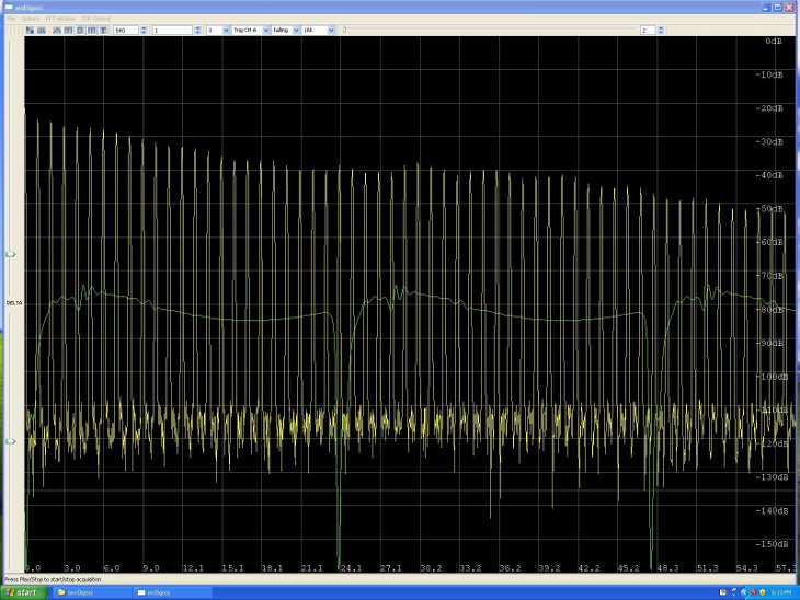
Figure 1. Sampler output viewed on Ultraview ADC board, showing heterodyne of train of pulses spaced 1.0101 ns apart (990.025MPPS), generated by on-chip pulser. Sampler is run at 990MSPS, resulting in 25,000 waveforms/second (40 microseconds of sampler output display corresponds to 1.0101ns of real time). Green trace is time domain display, yellow is frequency spectrum. Each comb tooth corresponds to a multiple of 990MHz contained in the pulse train. Zeroeth tooth at very left of window is DC, second tooth is 990MHz component, third is 1.980GHz, fourth is 2.97GHz, . last is 28.71 GHz. Combined frequency rolloff shown is due to roll-off of pulser energy multiplied by rolloff of sampler frequency response. At 9 GHz, sampler response is 3dB down from low frequency peaks, and pulser energy content is down 3dB, resulting in total depression of 6dB from low frequency response. At approximately 47 GHz, combined response is down 20dB, meaning that sampler and pulser response are each down by about 10dB from low frequency performance. Sampler response, and pulser energy combs are both usable to over 50GHz.
SAMPLER SPECIFICATIONS:
- Sample rate: 5MSPS to 1000MSPS (clock sources under 100MHz must be square wave)
- Number of channels: 2
- Full Scale Input range: +/- 200mV
- 3dB Input Bandwidth: 9 GHz
- 6dB Input Bandwidth: 18 GHz
- Usable Bandwidth while maintaining 40dB SNR: 50 GHz
- SFDR: 40dB at maximum input level
- Input connector type: 2.4MM Jacks
- Output connector type: Two SMA connectors:
- Output signal +/- 500mV peak, with adjustable offset voltage of 1 to 2V into 50 ohms.
DO NOT ADJUST ABOVE 1V WHEN USING DC-COUPLED 50 OHM LOAD
PULSER SPECIFICATIONS:
- Pulser clock inputs: Differential or single ended, AC coupled, amplitude 400mV p-p to 900mV p-p.
- Pulse repetition rate: 5MPPS to 2000MPPS (clock sources under 500MHz must be square wave with <100ps rise time - slower rise times will result in broader output pulse)
- Pulse amplitude (pulser may be disabled): Adjustable from approximately 30mV to 300mV
- Pulse width, at 2.4mm input/output connector: Approximately 16-22ps, viewed on HP 54750/54752A scope.
Demo Board Power Requirements:
- +5V at 210mA (typical), -6V at 560mA (typical).